Dagda – part two (cameras and computers)
So the last post was all about the mechanical chassis and frame and power systems; this time I want to look at the cameras and the computer.
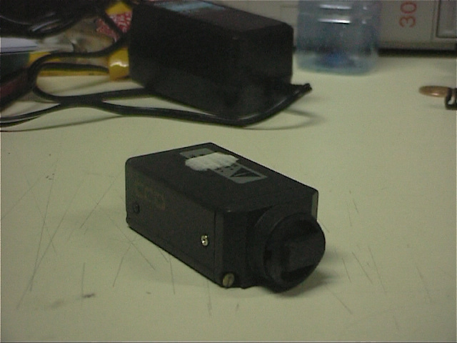
The cameras we used were standard research ones we had in the lab at the time – fairly straightforward things, whose resolution would now be too low to be used on the most basic mobile phone (and which were strictly grayscale only), but which were fairly high end at the time:
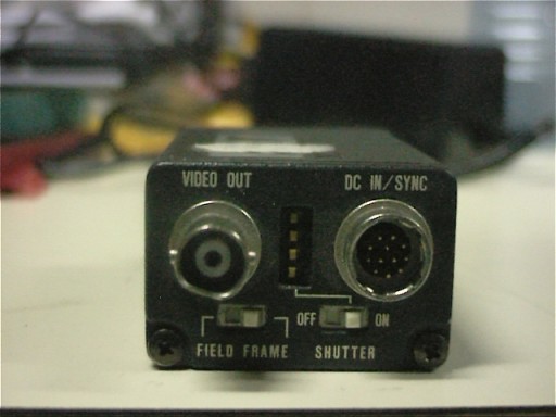
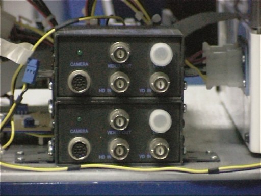
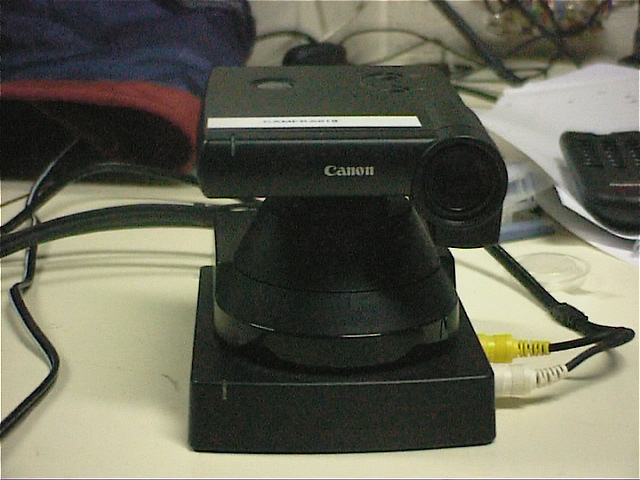
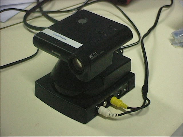
They were small and light, which was a plus, but they needed special cables and power supply boxes, which was a bit of a pain:
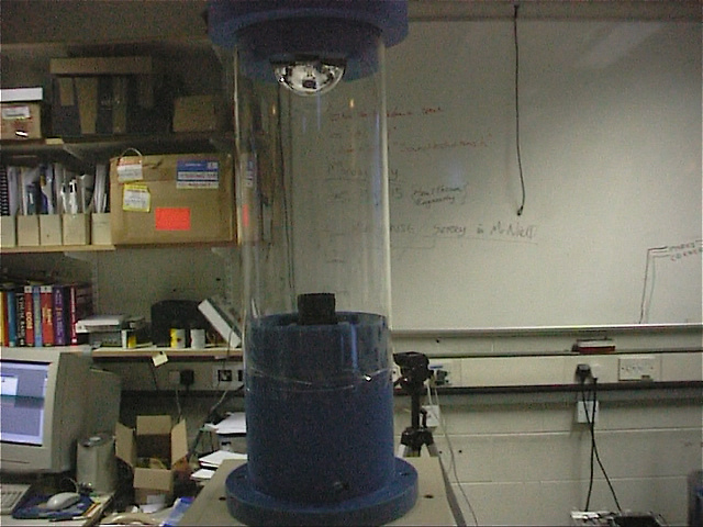
Still, they let us get video reasonably cheaply. We did have another camera sensor, mounted on the very top, which Niall Winters was using for his PhD which was on Omnidirectional Video – it was one of the first panaspheric cameras, and again, mostly home-made:
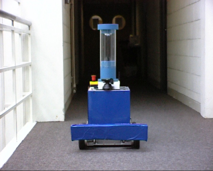
Custom-made moulded plastic base and top, vision-quality transparent perspex tube and custom-ground mirror mounted at the top. These days, you can buy these off-the-shelf; not so much back then! Niall’s initial work was capturing the image and “unwrapping” it to get a single undistorted rectangularish picture from the initial input image, and that would feed into our teleautonomous control system; but because his PhD was on a tangential topic to this, the two systems were kept as decoupled as possible. The camera itself was mounted at the very top of Dagda to get the best field of view:
At the base of Niall’s camera there is a pan-and-tilt camera, one of the more advanced cameras we picked up in the lab. The idea was that the panaspheric camera could give a general view to an operator, but the pan-and-tilt camera could zoom in to pick out any key details.
The canon was about the most polished camera we ever put on Dagda – today, it’d almost be considered an antique!
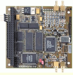
Of course all these cameras have to feed back into something, and in this case, it was a pc104 framegrabber based off the BT848 chip – which obviously means that you can use linux on the platform doing the computing.
Well, it was obvious back then at any rate 😀
As I mentioned earlier, we used a PC104+ platform for the main computer on Dagda. The thing to remember is that in its day, this was the top-of-the-line in embedded hardware, a real research system with far more processing power and memory space and disk space than any production design would have used; it ran linux (Debian 2.0.35 for those who remember 😀 ) to give a flexible development environment at a time when most embedded systems were in C if you were lucky. This was rather a big deal at the time – today almost every commercially built robot has some form of linux in it (and darn near all of the research platforms are linux based – and running python on your robot is no longer the prodigious feat it once was) but back then it was a novel thing to do.
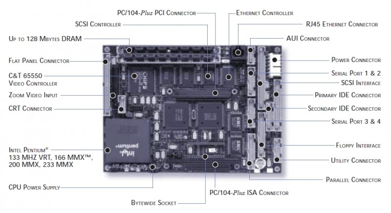
So when you learn that the system used a 200MHz original Pentium processor with a whopping full load of 128MB of RAM, don’t laugh too hard 😀 Here it is, the Ampro Littleboard P5e. You won’t find it on the web anymore, it was actually obsolete the first time we had to call tech support!
Stacked on the PC104+ expansion bus on that board was an Imagenation PXC200 framegrabber which had five inputs (four monochrome and one colour, multiplexed with a composite-video input). It was based on the BT848 chipset, but I had to write some custom tweaks to get the standard BTTV driver to work on it (those tweaks got accepted into the codebase, which was neat because that was the first really useful open source code I’d written).
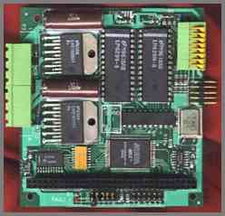
Stacked on top of the framegrabber was an Ajeco ANDI-SERVO motion control board with two output channels, which came with no linux driver – and that was the second useful bit of open source code I wrote (more on that in a later post).
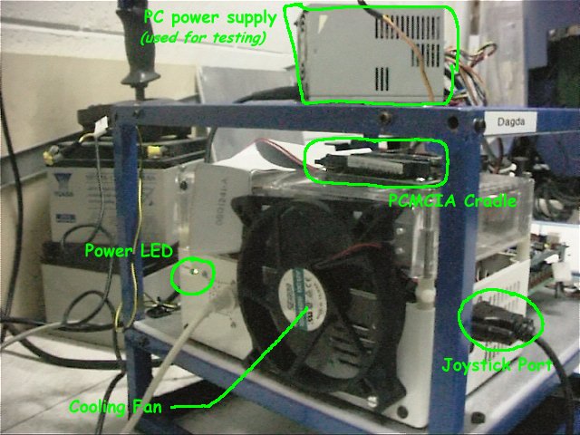
And stacked on top of that board was a PCMCIA adapter board. We didn’t actually add that until a bit into the project, when we got a very advanced wireless communication system in the computer science department (you might have heard of it, it’s called wifi today… 🙄 ). Another late addition was a high speed interface board to read a rotating laser scanner, but more on that later.
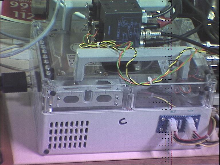
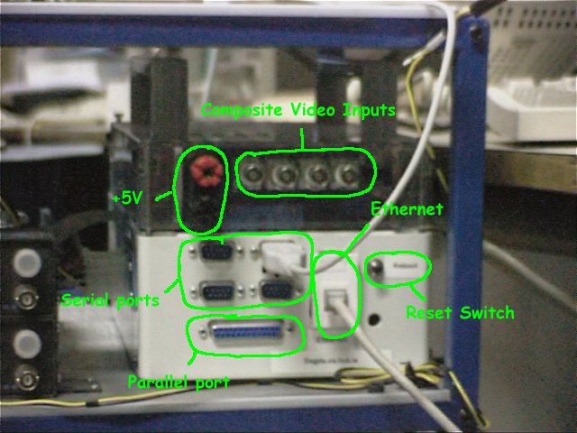
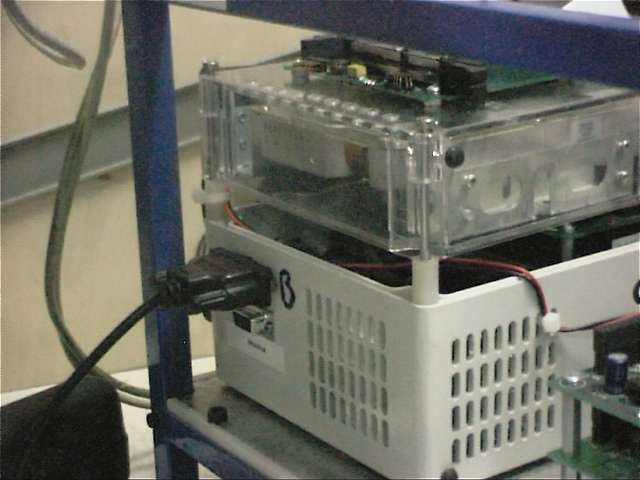
All of this kit needed a case (and somewhere to fasten the connector ports to), so a plastic box got ordered from Farnell and then sent off to be custom-cut to produce… *drumroll* the LunchBox! 😀
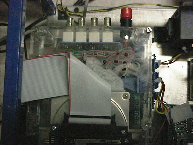
As you can see, we didn’t have SSDs or even laptop drives 😀 Over time, the handles up top were removed and the PCMCIA slot adapter installed there, and some other internal changes made, like the orientation of the disk drive and power take-offs for cameras and the like, but that’s the basic setup right there.
In the end, the Littleboard proved to be Dagda’s achilles heel. Late in 2001, it began to fail its boot sequence tests and would go into an endless rebooting cycle. It took some weeks to finally get an answer, but it finally got written off as being (in technical terms) “shot” by Ampro. By that point it was not just out of warranty, but fully obsolete (their closest match on their product line was about six versions removed from our board) and with the hardware budget coffers empty, that was the death knell for Dagda as it stood. It could still be restored (it’s still in the computer science department in TCD), if a new PC104+ board could be bought and fitted, but that’s neither likely to happen nor is it really a good idea, for reasons I’ll go into in the next post, on our laser scanning sensor, the later modifications to Dagda, and the lessons I learnt from building it.
[…] This post was mentioned on Twitter by Mark Dennehy and Mark Dennehy, Mark Dennehy. Mark Dennehy said: #StochasticGeometry Dagda – part two (cameras and computers): So the last post was all about the mechanical chassi… http://bit.ly/9KV9pa […]
[…] Part two of this article is now up here […]